Modifying a Servo for Continuous Rotation
The Daryl Sandberg Method
A very good way to power a robot is to modify an R/C servo motor. These are sold in hobby stores for use in model airplanes, boats and cars. They contain low voltage DC motors with gearing to provide lots of torque at an speed appropriate for robots. Most are designed to move within a +/-90 degree angle using a servo feedback potentiometer (for airelons, rudders, steering). For robotic uses the feedback needs to be disabled and replaced with a fixed resistor, resulting in continuous rotation.
These instructions are for Futaba FP148 servos. They will work with some other servos, but not all [this works with the Futaba S3003, except as noted in step 4]. They will not work with Hitec and Cirrus servos. The Futaba FP148 has a drawing of all of the servo parts that will aid you in performing this modification.
- Remove the four screws that hold the servo together.
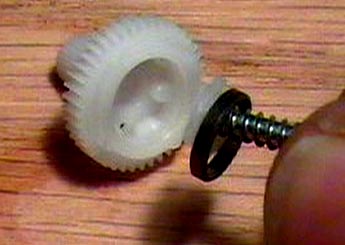
- Take the upper case off the servo by holding the upper case with your thumb and middle finger and pressing down on the final gear with your index finger. The cover should come off easily and all of the gears should remain in place.

- Remove the third gear and set it aside. Remove the final gear.

- Using a #6 sheet metal screw, remove the potentiometer drive plate that is inside the bottom of the final gear. Twist the screw into the drive plate about one turn and pull it out. The metal bearing will come out with the drive plate. Put the metal bearing back into the final gear.
[Note for Futaba S3003: the final gear in this servo has a molded-in flat that engages the potentiometer shaft; you will need to round it off using a dremel tool so that the pot shaft no longer turns at all when the gear turns]

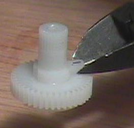
- Cut off the small protrusion that sticks up from the flat surface of the final gear. Trim it flush with the gear.
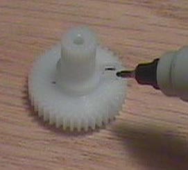

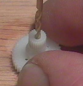
- Drill out the screw hole in the final gear. Use a 5/64" drill bit to make the hole go completely through the gear. Be careful not to damage the threads.
- Punch a small hole in a piece of heavy paper (like a business card). Place the card over the servo gears with the shaft of the potentiometer poking through the hole. This will protect the gears from metal filings in the next step.

- Using a razor or coping saw, cut a 1mm groove in the end of the potentiometer shaft. This will be used as screwdriver slot when the servos are calibrated.
- Optional: You can shorten the wires that go to the servo at this point. Do not attempt this unless you are very good at soldering in very tight places. This doesn't improve the performance of the robot, it just tidies things up a bit. Make them at least 100 mm long.
- Clean up all the parts and reassemble the servo. Put the final gear in place and spin it to make certain that it turns freely. Put the third gear in place. Put the cover on and screw it all together.

- Later, once the main circuit board is assembled and ready to be programmed, load the program servadj.bas, then, using a small jewler's screw driver (a nice set is available at Radio Shack), adjust the pot in each servo (through the hole you drilled in step 6) by engaging the tip of the screw driver in the slot you cut in the top of the pot shaft (in step 8), then turning slowly back and forth until the servo stops moving. The servos are now ready for use.
