Building Goliath
The Design
Goliath was my third attempt at a mini sumo robot. The first robot I built was a Marvin Slyder. It was fun and a great learning experience, but I knew it would never be a serious contender. I started to build another mini sumo with a brass frame and a very low center of gravity. I used one inch sprockets and timing belts covered with silicone sealer. It had great traction standing still, but would quickly do a wheely when it encountered another robot, losing traction. My next attempt was a fairly conventional looking mini sumo but with a solid brass frame. It had three inch disks for wheels and I used silicone sealer for the tires. I later used tires cast by Bob Sutter out of urethane mold making compound. It was very competitive but just plain ugly.I took what I had learned from the previous projects and began to design Goliath. I started with the wheels and tires. Experience showed me that traction was the most important thing if you want to win. Processing power, sensors, and strategy mean absolutely nothing if you can't push the other robot out of the ring. The goal was to get as much rubber on the ground as possible. The greater the width and the greater the diameter of the tire, the better the robot would perform.
I played with different layouts on my CAD program (Autosketch 7). Some things were constants. Two servos, 4 AA batteries and a little space for sensors and a Stamp 1. There just wasn't much room for any significant changes.
The rules state that a robot can have a footprint of only 10 centimeters square to qualify. But the robot can get larger once the contest starts, as long as it stays in one piece. A robot can be any height. So if the robot started in the begging dog position, then dropped down after the contest started, you could have a real advantage.
Once I decided to go with the drop down strategy, everything got easier. Now there was a lot more room to play with. The inside diameter of the wheels (63 mm) was determined by the size of the servos (with the mounting ears cut off) because the servos are inside the wheels. The outside radius was determined by adding the thickness of the AA batteries in the case, and one half the thickness of the servo plus the thickness of the chassis bottom piece plus a little bit for ground clearance. This came out to a 35 millimeter radius, or a 70 millimeter diameter. The width was determined by subtracting the width the battery pack from 100 mm and dividing by two. I used a long and thin 2X2 battery pack mounted between the tires, instead of the normal 4X1 underneath.
Once I decided to go with the drop down strategy, everything got easier. Now there was a lot more room to play with. The inside diameter of the wheels (63 mm) was determined by the size of the servos (with the mounting ears cut off) because the servos are inside the wheels. The outside radius was determined by adding the thickness of the AA batteries in the case, and one half the thickness of the servo plus the thickness of the chassis bottom piece plus a little bit for ground clearance. This came out to a 35 millimeter radius, or a 70 millimeter diameter. The width was determined by subtracting the width the battery pack from 100 mm and dividing by two. I used a long and thin 2X2 battery pack mounted between the tires, instead of the normal 4X1 underneath.
Building the chassis
I began building the chassis out of brass. All the robots I had built up to this point had been well under the 500 gram limit and required adding lead weight to bring up the mass. I cut out the pieces and put them on the scale with the batteries, servos, and circuit board. It was clear that the brass frame was going to be too heavy. Acrylic was too brittle, aluminum was too difficult to build in this configuration, so I chose 1/16" Lexan (polycarbonate). I bought a couple of pounds from the scrap heap at Tap Plastics.
The base of the frame is 150 mm by 95 mm with cutouts for the wheels that are 30 mm wide and 57 mm long. On top of that is the battery box. It's 110 mm long by 35 wide (outside) and 19 mm tall. There is a bulkhead in the front to mount the DigiKey line sensors (QRB1114QT-ND). The mounting loop molded into the top of the sensors is chopped off to reduce the height.
On top of the battery box is the vertical mounting sail for the servos. The back covers of the servos are removed and the cover mounting screw holes are drilled completely through the servo body. This allows four 2-56 threaded rods to go completely through both servos and the mounting sail on the chassis. This makes for a strong mount and puts the servos closer together, making more room for tires and wheels.
On top of all this is the mount for the circuit board.
Making the body
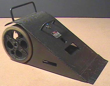
I didn't want another ugly robot. This robot was going to have a body and look cool. The design was already laid out on the computer, so it was just a matter of figuring out how to build it.
The decision was made early on to use carbon fiber. It looked great, it was light, and it was strong. I started by making a mock up out of 1/32 inch aircraft plywood. I used a heat gun to soften the glue so I could curve the the top piece over a form to give it a radius to go over the wheels. I super glued the triangular side pieces on. Then I used a three inch drum sander to round out the openings for the wheels in the side pieces.
My original intent was to use the plywood mock up as a master for a mold. But I weighed the plywood mock up it and it hardly moved the scale so I decided to lay up the carbon fiber right onto the plywood. I had plenty of carbon fiber cloth since I bought a one foot by four foot piece at Tap ($12.00). Carbon fiber cloth is just like fiberglass cloth except it's stronger and black and it doesn't itch. It's a little harder to cut with scissors, but certainly not as tough as Kevlar. I used Tammy's slow curing finishing epoxy to bond the carbon fiber cloth to the plywood.
It came out OK. I made some mistakes that forced me to put lots of epoxy on to level the top. It was a bit concave at first. Here's a tip, don't start laying up carbon fiber a half hour before BattleBots comes on. At 45 grams, it weighs a bit more than it needs to but it's acceptable. I could probably cut this down to 30 grams without losing any strength if I had stuck with my original plan and left out the plywood and was also thrifty with the epoxy. If I had made the body out of 0.050 aluminum, it would have weighed 55 grams. All in all, it came out pretty good. It's very strong and flexible, but most important, it looks really cool.
The rules say that there can be no sharp edges. "Sharp" has been defined as anything with a radius of less than 0.005 inches. I used a piece of 0.010 spring steel for a front scraper on Goliath. Since half of this is 0.005 (two 0.005 radii on the edge of the spring steel), anything that gets under Goliath's scraper is illegal. The scraper is attached to the very front edge of the robot with servo tape. That give it just enough flex to match any irregularities in the surface of the ring and provides a way to get under the other robot.
Wheels and Tires
Goliath's wheels and tires define its performance more than anything else. They produce extraordinary traction. Anything more would be against the rules.
The tires are a mixture of Tap Plastics Urethane RTV System A (one part), B (one part), and Polytek Poly 74 Series RTV Liquid Rubber Part C (one part). Bob Sutter gets all the credit for the formula. Making tires out of this stuff is messy and time consuming, but nothing beats the traction. The mini sumo rules state that you cannot use sticky tires. "Sticky" is defined as a tire that will pick up a 3X5 note card for 5 seconds. A clean tire made with this mixture will lift a piece of paper about half an inch before dropping it. Like I said, anything more would be against the rules.
The tires are cast right onto the wheels. I built a three piece mold out of poplar and sealed the wood with epoxy. This is important. It seems that if you don't seal the wood really well, the wood will out-gas and your tires will be filled with irregular bubbles. A little paste wax keeps the compound from sticking to the mold. Casting the tires to the wheels does not provide enough adhesion to stand up in competition, so I used super glue to tack the tires to the wheels.
The wheels were a lot of work. I looked for weeks trying to find something that was cup shaped and just the right size to make the wheels. They had to be 63 mm inside diameter. I could go up two or down one mm, but that was it. They had to be at least 30 mm wide. Nothing.
I ended up fabricating the wheels out of 0.050" aluminum. I cut two strips 30 mm wide and 200 mm long. I rolled them into a cylinders with a shear/brake/roller that I got at Harbor Freight for about $200. This is a great tool and has saved me a lot of time and made some projects possible that I wouldn't have been able to make any other way.
I cut a disk out of the same aluminum and brazed the two wheel pieces together with some Forney Easy Flow aluminum rod that I got at the local Ace Hardware Store. I used a propane torch but with MAPP gas. Burns hotter and makes the process go quicker. The heat warped the disk a bit and it took some reheating and tweaking to get the wheels to run true but they are good to about 0.030". They are susceptible to bending if you drop the robot but they have never been damaged in combat.
A normal servo horn will not work! You have to use a heavy duty horn or the splines will get stripped out with all the torque and traction. When the splines strip, the wheel just spins off because the screw comes undone. It's embarrassing when your wheels roll out of the ring and across the floor during a match.
After I got Goliath put together, I weighed it and it was about 30 grams too heavy. I could drill some holes, but even with that there was too much fat. I looked at all of Goliath's components and decided that the wheel/tire combination was the best bet for liposuction.
I tried a few different things, but I finally ended up recasting the tires. I stripped the original tires off the wheels. I cut a strip of 1/8 inch closed cell neoprene foam and glued it to the rim with contact cement. The strip was 22 mm wide and about 200 mm long. I put the wheel back into the mold and cast a new tire around the neoprene foam. It worked great. It cut 15 grams out of the weight of each wheel. It also made the tire more flexible because the foam acted like an inner tube. Goliath was back in business and out of the fat farm.
Sensors and controller
Goliath uses four Sharp GP2D15 digital sensors to detect the other robots. These have a range of about 240 mm. They are great. I spent a lot of time trying to get sensors with a longer range. I tried to trick the Sharp GP2D12 analog sensors to give a digital signal with a range of 800 mm. Worked great on the bench but not on the robot. Now Sharp has available the new GP2Y0D02YK sensor that has a range of 800 mm. I've tried them on another robot and they are superb. It's not likely that I'm going to put them onto Goliath.
Two Digikey QRB1114QT-ND reflective IR detector emitter pairs are used to detect the white line. A 10K pull down resistor is used to bias the detector and a 1K resistor in series with a 5K pot is used to light the IR emittors. The sensors sit about 5 mm off the deck.
Goliath uses a Stamp 1 for it's brains. It sits on a Marvin Green Explorer Bot circuit board. This is a really handy board for the Stamp 1. It can be adapted to most applications without difficulty. It's a great deal at ten bucks, but I don't know if Marvin still sells them. I used this processor because I can program it and it certainly has enough poop to handle this simple application. See it, attack it. Don't go off the board. Not a difficult program.
The program is set up with few pauses. Typically, a program to run two servos forward where the neutral point was set at 1.5 milliseconds would be something like:
FORWARD:
 for ticks = 1 to 10
 Pulsout Lmotor 200
 Pulsout Rmotor 100
 pause 15
 next
SCANSENSORS
I set the neutral point on the servos to 0.8 milliseconds. I don't use a pause. I use this time to scan the sensors.
FORWARD:
 For ticks = 1 to 10
 Pulsout Lmotor 100
 Pulsout Rmotor 50
 Gosub SCANSENSORS
 next
Goto FORWARD
The time spent scanning the sensors creates enough of a pause. With this program, a lot more time is spent scanning the sensors (about twice as much).
The program puts a priority on attacking the other robot. This takes precedence over the line sensors. When a target is in sight, the line sensors are ignored. I did this in response to my own strategy. Previous robots that I have built have had a spatula like appendage on the front to get under the sensors of the opposing robot and trick that robot into thinking that it was on the white line and consequently make it back up. I didn't want that to happen to Goliath.
Goliath doesn't run at full speed when it is looking for another robot. At full speed, Goliath will be going too fast when it approaches the edge of the ring and be hanging over the edge before he can reverse and back up. It wouldn't take much of a nudge from another robot to push him out. Running at a slower speed allows Goliath to swing around, without reversing, to avoid going off the ring. This means that it is always going forward. This is very important. Robots can get confused when locked nose to nose with another robot. I've seen robots go into reverse when they wheely up onto another robot because the line sensors catch a reflection of the other robot. Not a good battle strategy.
Servos
Goliath uses two Hitec 945MG servos. These are high torque, high speed, high buck servos with metal gears. They are quiet and tough and they match the traction of the tires well. There is no point to having high torque servos with mediocre traction. Conversely, high traction with weak servos is certainly no winner either. They are modified for continuous rotation by pulling the link out of the output gear that drives the feedback pot. The end of the shaft of the feedback pot is then slotted with a razor saw to take the blade of a small screwdriver. The output gear screw hole is drilled straight through so that the feedback pot can be adjusted when the servo is fully assembled and mounted on the robot. Just take out the screw that holds the servo horn on and slide a small screwdriver into the hole to adjust the servos to neutral at 0.8 ms.
There is a pin in the output gear that blocks full rotation. This pin can easily be removed with a pair of needle nosed pliers.
As stated in the Sensors and Controller section, the servos are set so that 0.8 milliseconds is neutral, not the 1.5 milliseconds that is normally used.
The Laser
The laser is primarily just for show. It also serves as an indicator LED to show that Goliath is powered up. The laser came from a key fob pointer that I got at Fred Meyers for about $7.00. A lot of people think that it functions as some sort of sensor or aiming device. I wish. But usually if the laser is hitting the other robot, the Sharp sensors have the robot in view also and Goliath is in fast attack mode and the end is near.