|
Connect the Proximity Sensors
If you are using the sensor board that comes with the Mark II kit, follow
these instructions:
Cut a 4" length of the 4 conductor ribbon cable:
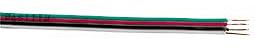
Note: the wire in your kit may have different colors;
just use the colors to keep track of which wire goes where.
There were mistakes in the instructions below.
The corrections are in white bold lettering.
Separate the wires for approximately 0.5" in from each end, and
strip off approximately 1/8" of insulation from the ends of each
wire. Solder the wire in place as follows:
- On the sensor board, solder the green wire in -,
red in +, black in L
(unlabelled on some boards), and white in R,
with the wires entering the holes on the board from underneath.
- NOTE: for kits number 1-26, you need to solder 120 ohm resistors
in series with L and R to limit current in to the sensor's outputs
if the Basic Stamp is programmed by mistake to drive out on those
signals; see the PDF version of the instructions for details
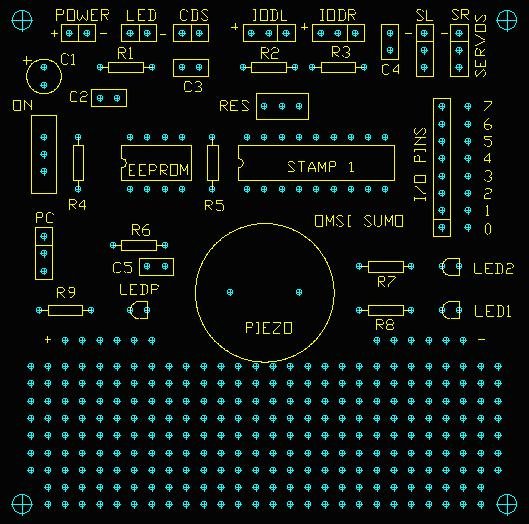
- On the main board, solder the green wire to the -
hole on IODR (the center hole), the red in the +
hole of IODR, the black in the square hole of IODL, and the
white in the square hole of IODR
- When the main board and sensor board are attached as described below,
route the ribbon cable out of the way of the piezo speaker, LEDs,
and I/O pins.
If you are using the Sharp GP2D15 sensors, follow these instructionrs:
The IODL and IODR connectors
are soldered to the circuit board in the IODL and IODR holes. The red
wire is positive, the black wire is ground, and the yellow wire is the
signal. The signal wire goes in the square hole, the ground goes
in the center hole, and the positive goes in the + hole.

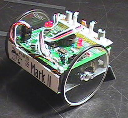
Attach the Main Board
If you are using the sensor board, attach the circuit board to the four
stand-offs with two 4-40 pan head screws in the back and two 3/16"
male-female stand-offs in the front. Tighten the four screws on the bottom
and the two screws and two stand-offs on the top.
If you are
using Sharp GP2D15 sensors, attach the circuit board to the four stand-offs
using the four 4-40 pan head screws in all four corners. The two 3/16"
female stand-offs are not needed.
Using the last piece of double stick tape, attach the battery holder
to the bottom of the chassis. The wires should be at the right rear corner
of the robot, looking at it as if you were driving a car. The front edge
of the battery holder should be 1/8" behind the bend in front of
the chassis. Tape the wires to the right rear aluminum stand-off with
electrical tape.
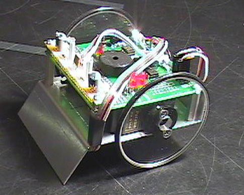
Attach the Sensor Board
If you are using the sensor board, attach the sensor board with the
two 4-40 pan head screws to the top of the 3/16" standoffs. The IS471F
sensors and IR LEDs should be pointing forward.

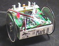
Weight Limits and Size Limits
The OMSI mini sumo robot
when completed weighs about 320 grams. The mini sumo competition allows
robots to weigh up to 500 grams. Add more weight to give the robot better
traction. Tip: place the weight towards the front to help hold
the scoop down.
All Mini-Sumo robots must
be equal to or less than 10 cm square; they can be any height. Ten centimeters
is close to 4", but not quite. It's slightly less than 3 15/16".
When your robot is checked in the day of the competition, it will be weighed
and placed within a 10cm by 10cm box; if it fits and does not weigh too
much, you are ready to complete. If it is too big or heavy, you can't.
You can make a practice ring by using thick black poster board and paint
or tape a one inch white edge. The regulation mini sumo ring is 77 cm
in diameter and is covered with a layer of black rubber.
|

