Programming the Basic Stamp I
 Download Basic Stamp
Editor Version 2.1 and Examples. Download Basic Stamp
Editor Version 2.1 and Examples.
 Stamp programs: Stamp programs:
Servo Adjust Code
- code for zeroing out the servos so they don't rotate when 1.50ms
pulses are sent
PARTS Mini
Sumo Mark II Code - for non-rotated servos
and PARTS IR sensor board
PARTS Mini Sumo Code -
for rotated servos and Sharp GP2D15 sensors
Programming the PARTS Mini-Sumo Robot
The
PARTS Mini-Sumo Robot is programmable in a version of BASIC called
PBASIC. PBASIC is not a full featured BASIC, but it is flexible
and easy to use. You will need to review the BASIC STAMP's documentation
from Parallax to learn all the commands and functions of PBASIC.
Note: The STAMP.EXE editor may not work well under Window's 95/NT.
Exit Windows and run the editor from the DOS prompt.
There
are 8 input/output pins connected to the BASIC STAMP 1. Each of
the 8 pins can be designated as an input or an output.
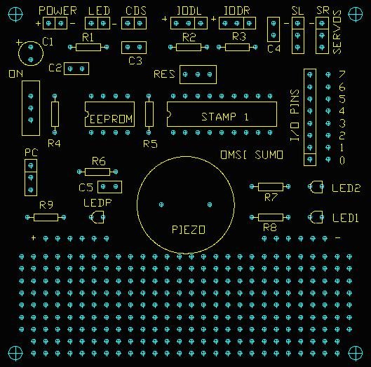
This robot uses all 8 input / output pins:
Pin 0 - PIEZO Speaker
= output
Pin 1 - LED1 = output
Pin 2 - LED2 = output
Pin 3 - SR Right Servo Connector (- = black wire) = output
Pin 4 - SL Left Servo Connector (- = black wire) = output
Pin 5 - IODR Right IR. Object Detector (+ = red wire) = input
Pin 6 - IODL Left IR. Object Detector (+ = red wire) = input
Pin 7 - CdS resistor detects light level = input
|
