|
|

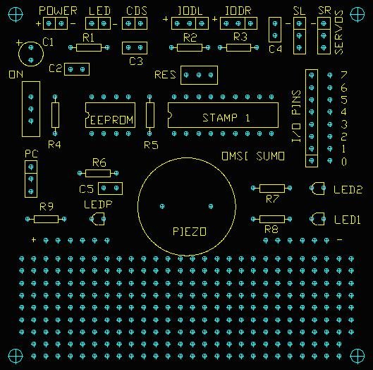
This picture is from the Mark I robot, but will
be the same for the Mark II except for R2 and R3. R2 and R3 do not
need to be used with the sensor board, only with the Sharp GP2D15s
if you choose to go that route.
|
The
line sensor that is mounted under the scoop uses an LED to provide
light and a CdS sensor to measures the amount of reflected light.
Solder two 6.5 inch wires to the CdS sensor and solder the wires to
the CDS location on the circuit board.
Solder two 6.5 inch wires to the LED. The LED is polarized. Make note
of the cathode side (click here
to help you determine the cathode side of the LED) and make sure that
it get connected to the ' - ' side of the LED connector on the circuit
board.
Mount the CdS sensor and LED to the underside center on the front
scoop, making sure that the bare wires do not touch the metal scoop,
and that the CdS and LED do not rub on the table when the robot is
running. A hot glue gun is perfect for this. The line sensor will
not work well if the CdS and LED are too far away from each other,
are pointing away from each other, or are pointing so much towards
each other that the CdS is seeing the LED directly.
|
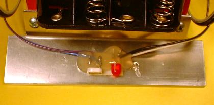
Note: this is a picture from
the Mark I robot, but the Mark II will be very similar.
|
|
