|
Introduction
Assembly
Testing
IR Shields
Experiment
|
|
Click on an image to see a larger version.
|
Introduction
The sensor board for the PARTS Mini-Sumo Robot Mark II uses 2 Sharp
IS471Fs, 2 Infrared LEDs, and a few other parts. It can sense
objects up to 8-10 inches away, depending on reflectivity. Best
of all, it's pretty inexpensive.
This board was designed by Marvin Green, for use in the PARTS Mini-Sumo
Robot Kit, Mark II. Good job, Marvin!
|
|
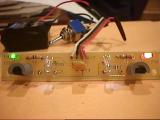
Note: these pictures are of an early prototype,
so certain details will be different from the kit.
The prototype used 1/4 watt resistors, jumpers
on the bottom of the board instead of 0 ohm resistors, and rectangular
green and amber LEDs instead of round. The prototype did not use
the miniwrap terminals nor the spacers for the IR LEDs.
|
Assembly
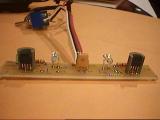
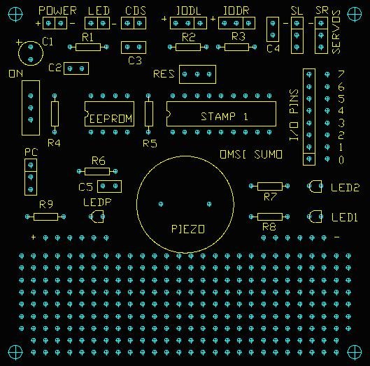
The parts indicated on the sensor board layout below are:
- IS1, IS2 - Sharp IS471F sensors; the flat side faces forward
- LED1 - green LED; cathode in square pad
- LED2 - amber LED; cathode in square pad
- IR1, IR2 - infrared LEDs; cathodes in square pads
- R1, R2 - 0 ohm resistors or jumpers; if you use a wire for a
jumper, place it on the back of the board to avoid shorting out
IR1
- R3, R4 - 1K ohm resistors if low-current LED1 and LED2 are used;
otherwise use 330 ohm resistors
- R5, R6 - 120 ohm 1/4 watt resistors in series with the sensor
outputs for current limiting in the event that the Basic Stamp
is misprogrammed or unprogrammed, and drives the sensor input
lines high (otherwise known as the phffft effect!)
- C1 - high-frequency bypass capacitor (preferably multilayer
ceramic), 2.5mm radial lead spacing, 0.68 uF or higher
- P1 - connection to main PCB via 4 conductor ribbon cable
|
|

Sensor Board Layout
|
|

note the position of the front of the IR LEDs
compared to the front of the sensors
|
First, solder in R1 and R2. These are the small resistors with
only a single black stripe on them, which means 0 ohms. They are
used as jumpers, as it turned out that R1 and R2 were not necessary
to the design.
Next, solder in R3 and R4, the 1K ohm resistors (brown, black,
red). Solder in the capacitor C1.
Resistors R5 and R6 are current limit resistors that must be added
in series with the L and R output pins of P1, before the signals
get to the main board. The original 25 kits do not have places for
these resistors on the circuit board. Instead, this can be done
by soldering one end of each 120 ohm resistor into the respective
L and R holes on the sensor PCB, and allowing the other ends of
the two resistors to hang loose until later.
When the ribbon cable is added to connect the sensor board to the
main board during final assembly, solder
the L and R wires from the main PCB to the loose ends of the two
resistors, then protect their ends from shorting on the main PCB's
prototype area using 1/2" lengths of heat shrink. Tip:
peel the L and R wires away from each other and from the + and -
wires for about 2", then slide the two heat shrink tubes down
the wires as far as you can from the solder joint. Then, solder
the stripped ends of the L and R wires to the resistors, let cool,
then slide the heatshrink back over the exposed ends of the resistors.
Now rub the heatshrink briefly with the tip of the soldering iron
to shrink it. If the heat shrink is too close to the solder joint
during soldering, it will shrink too soon and won't be able to be
slid over the solder joints.
Now you can add the IS471Fs. See the images on this page for proper
device orientation -- the bumpy side goes towards the back of the
board, facing R3 and R4, while the flat side faces forward. Insert
an IS471F into the four pads, all the way down to where the pins
straighten out, then solder them in.
Next, attach the green LED, in the LED1 spot. The cathode is the
short pin on the LED, and goes in the hole with the square pad.
The cathode is also marked by the flat side of the LED. Then, attach
the amber LED in the LED2 spot, again with the cathode in the square
pad hole. If they are backwards, they will not light.
Now it's time to add the IR LEDs -- the two clear ones. There are
three methods for mounting them, not all of which are possible with
some kits (kits #16-26 are missing the LED spacers):
[do JUST ONE of the following:]
- bend the leads of the LEDs in the right shape, and solder them
in
- use 2 vector miniwrap terminals (included in the kit), snap
the LED leads into the forks in the top of the terminals, then
solder the connections
- use 2 vector miniwrap terminals on either side of the LED spacer,
then attach the LEDs to the terminals as in 2; use heatshrink
to protect from shorting.
The method you use depends on the parts present in your kit, as
well as your comfort level in severely bending LED leads. Method
1 is the normal method used in boards like this, but due to the
placement of the LEDs compared to the sensors, the leads must be
bent even sharper than normal. The metal used in LED leads is brittle,
and must be bent slowly and carefully or it will snap, often right
at the base of the LED, rendering it useless.
|
|
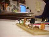
Hey, it works!
|
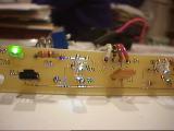
Testing
The sensor board is easy to test. As explained in the final assembly
page, solder in a length of the 4 conductor ribbon cable to the
P1 area. Then, temporarily connect the battery case's wires to the
ribbon cable by twisting the ends together:
P1 '-' = ribbon cable green = battery black
P1 '+' = ribbon cable red = battery red
make sure the red and black wires don't short together, and that
ribbon cable white and black also do not short to anything
Insert some fresh batteries in the holder. If neither colored LED
lights, hold a white piece of paper or your hand in front of the
sensor board, about 4 inches away. One or both of the green and
amber LEDs should light up, if they are not already. If neither
lights up, remove at least one battery from the holder, then check
the board. Are there shorts caused by blobs of solder where there
shouldn't be? Are the LEDs in the correct way? Did you wire up the
battery holder correctly?
If the green and amber LEDs work, it's time to attach the IR shields.
|
|
See how the shields are slightly bowed-out away from the IR
LEDs to block direct light from reaching the detectors
|
Installing the IR Shields
Place a shield around the back side of an IS471F, with the bottom
edge of the shield flush against the PCB. Using your thumb and forefinger,
gently squeeze the shield onto the sensor until it feels engaged,
with the shield rotated vertically slightly so that the edge of
the IS471F is blocked from view of the IR LED. Don't rotate the
shield too far, or else it won't stay on and it will be blocking
the front surface of the sensor from valid IR reflections.
At this point, you should be able to shake the board and the shield
will not fall off. Hold the PCB pointed away from any objects (towards
a non-reflective wall at least 3 feet away), see if the LED on that
side of the board has gone out. If not, gently remove the shield
and rotate it slightly, then try again. Do the same for the other
IS471F.
You may need to use a tiny drop of super glue on the bottom of
each sensor shield to prevent them from dropping off -- especially
during a competition! Just be careful, and don't get any super glue
on the LEDs or the fronts of the sensors.
Finally, remove the batteries from the holder, untwist the wires,
then go on to the next step.
|
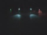 |
Fun Experiment (if you have a webcam)
This is what IR looks like! The blue-ish beams are from the IR
LEDs, as detected by a 3Com BigPicture webcam with the room lights
off. The CCD element of a digital camera can see in infrared.
You can try using this when you are done assembling your robot
to fine-tune the aiming of the IR LEDs.
|
|


