|
The
robot uses two Futaba 3003 or similar radio control servos. Click
here for an explanation of how servos work. These servos are
designed to rotate about 180 degrees and need to be modified to
rotate continuously.
Servos
are ideal for small robot use because they contain a motor, gearbox
and motor drive electronics. And, servos can be controlled with
only one I/O pin, which is very nice when using a microcontroller
with limited I/O as in the Basic Stamp I used in the kit.
NOTE: Servos are not included in the kit. You must purchase them
separately.
At least one vendor, MrRobot.com,
sells pre-modified, continuously rotating servos, which is a much
easier route for begineers. However, this is not an endorsement
of MrRobot.com or its products.
|
|
Optional Additional Servo Modification #1:
Note: if this is not done, be sure to
use the version of the program available for download which is designed
for unrotated (identical) servos!
One servo should be modified to rotate
the opposite direction of the other servo. This is because the servos
are placed facing opposite directions of each other on the robot
base.
This will make programming the software easier because using the
same pulse width value for both servo's, will drive one servo clockwise
and the other servo counter clockwise. This will move the robot
forward or reverse.
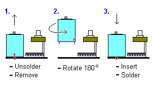
To perform this modification on one servo you will need to remove
the motor and circuit board from the case. The motor is attached
to the circuit board by two solder tabs. To remove the motors, remove
the solder from the solder tabs using a solder sucker, solder wick,
or tapping the circuit board until the heated solder falls off.
Once the solder is removed and the motor is separated from the circuit
board rotate the motor 180 degrees and reinsert the motor and solder
it back into place.
 Not necessary if your program accounts for the
difference in direction between the two motors Not necessary if your program accounts for the
difference in direction between the two motors
|
Additional Servo Modification #2:

Both servos should be adjusted to the same neutral value.
Click Here
Using the same neutral value for both servo's makes coding the software
much easier because the same value can be used for both servo's.
If you use Daryl's instructions
for modifying a servo, step 11 describes how to zero the pot; you
should not do what follows.
This
adjustment can be accomplished by using the BASIC STAMP program
SERVADJ.BAS to send a pulse width of 1.50ms to each servo. Adjust
each servo's potentiometer to it's neutral position. Put a drop
of superglue on the potentiometer, then cut off the shaft of the
potentiometer with bolt cutter or push it down into the servo case.

Not necessary with Daryl's servo hack
|
